Electrical adequacy
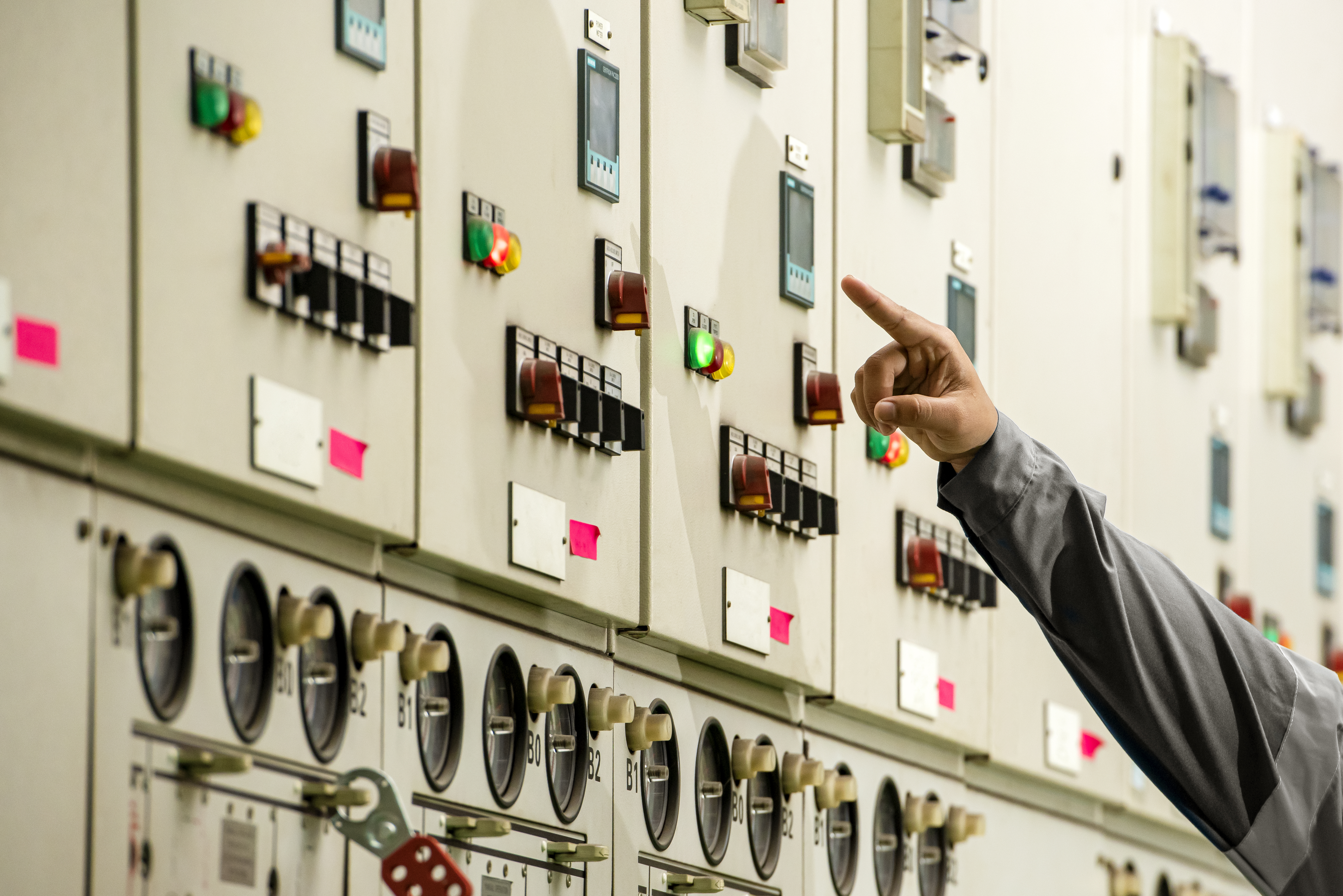
Bus and conductor sizing for continuous and fault duty, equipment ratings verified against calculated fault current, and clearances to the applicable standard.
Review this service area →Physical and electrical design for transmission and collector substations — one-lines, general arrangement, grounding, bus sizing, equipment specification, and support through energization.
Physical and electrical design for transmission and collector substations — one-lines, general arrangement, grounding, bus sizing, equipment specification, and support through energization.
Bus and conductor sizing for continuous and fault duty, equipment ratings verified against calculated fault current, and clearances to the applicable standard.
Review this service area →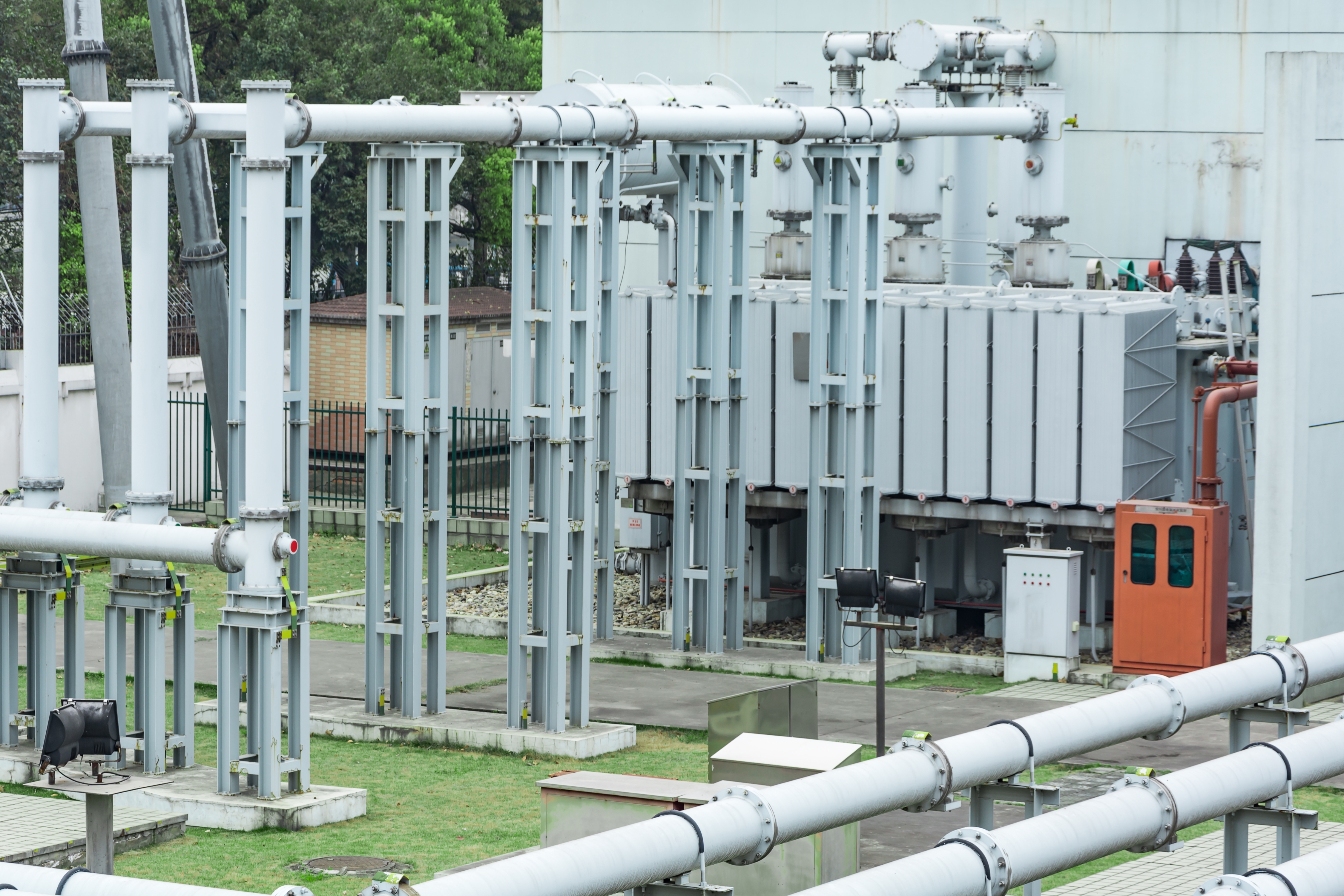
Grounding grid designed to IEEE 80, with step and touch potential verified against the actual soil model and clearing time.
Review this service area →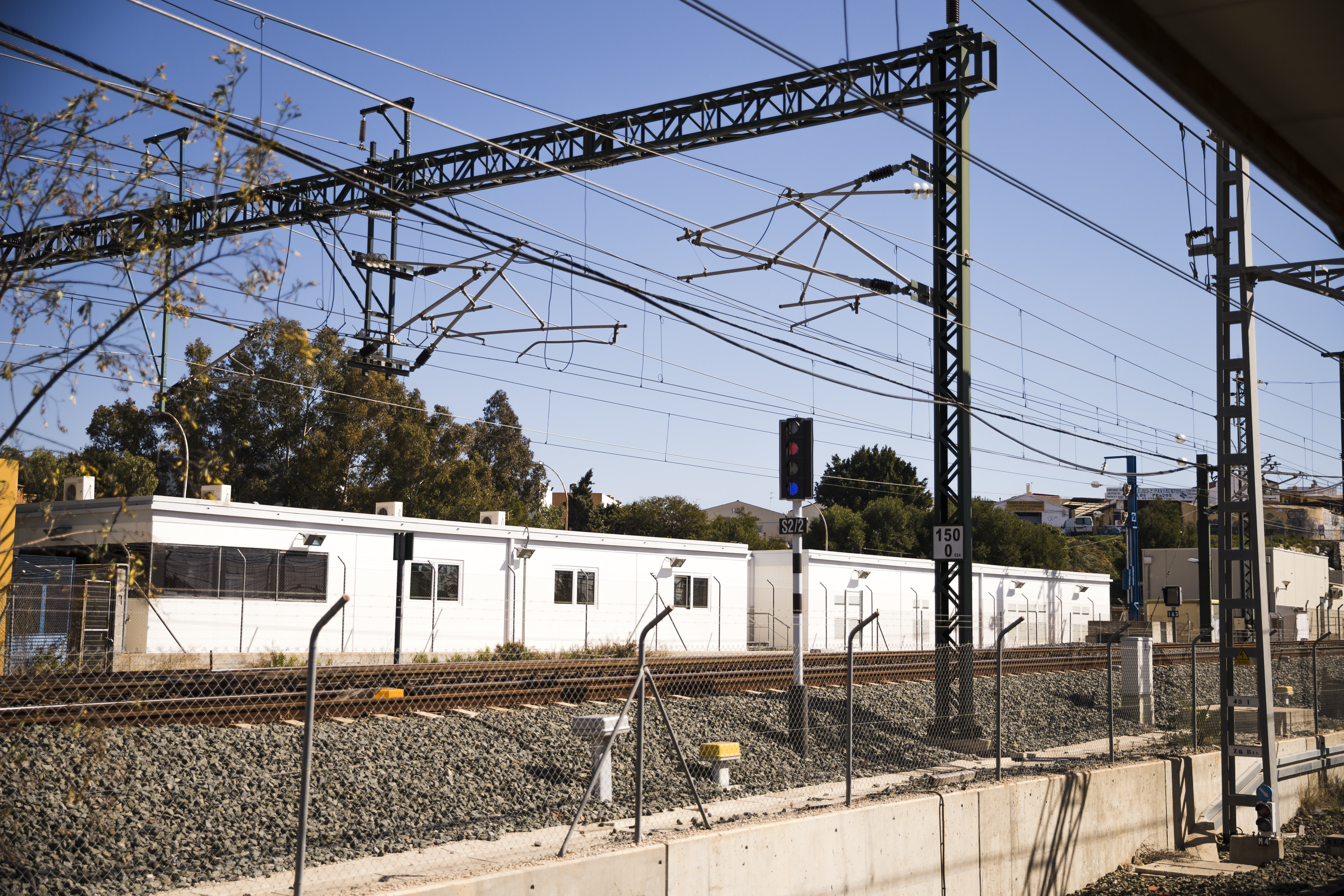
A design developed to reduce RFIs during construction. General arrangement, foundation loads, conduit and cable schedules, and equipment access.
Review this service area →A substation package only works if the drawings, equipment ratings, and grounding all line up with how the project will actually be built.
How our engineers work →Bus and conductor sizing for continuous and fault duty, equipment ratings verified against calculated fault current, and clearances to the applicable standard.
Grounding grid designed to IEEE 80, with step and touch potential verified against the actual soil model and clearing time.
A design developed to reduce RFIs during construction. General arrangement, foundation loads, conduit and cable schedules, and equipment access.
Trusted analysis and design platforms, applied by engineers who understand the system behind the model.










Physical and electrical design for transmission and collector substations — one-lines, general arrangement, grounding, bus sizing, equipment specification, and support through energization.
Voltage, bus configuration, ratings, applicable standards, owner preferences, and site constraints agreed in writing before drawings start.
One-line, general arrangement, preliminary equipment list, site layout.
Three-lines, AC/DC schematics, grounding, conduit and cable schedules, foundation loads, bill of materials.
Issued-for-construction package; professional sealing provided where required and within the responsible engineer’s jurisdiction.
RFI response, submittal review, field changes, and as-builts.
Voltage level and design boundaries are confirmed during project scoping.
30% establishes configuration and footprint. 60% adds three-lines, schematics, grounding, and preliminary schedules. 90% is essentially complete and ready for owner and AHJ review.
Because step and touch potential is a life-safety calculation, and it depends on the actual soil resistivity at your site, the actual available fault current, and the actual protection clearing time.
Yes, and it’s increasingly necessary. Transformer and breaker lead times have driven many projects to design around whatever can be procured rather than what’s ideal.
Professional sealing is provided where required and within the responsible engineer’s jurisdiction.